
Now Reading: Relay Module with ESP32 DOIT Kit v1
-
01
Relay Module with ESP32 DOIT Kit v1


Introduction
A relay module is an electrically operated switch that allows your ESP32 to control high-voltage or high-current devices like lights, fans, motors, and other home appliances. Since the ESP32 operates at 3.3V logic and can’t directly handle high power loads, the relay acts as a bridge between low-power control (ESP32) and high-power devices (AC/DC).
Relay modules typically have:
- VCC (5V or 3.3V depending on module)
- GND (Ground)
- IN (signal input, connected to ESP32 GPIO pin)
- COM, NO, NC (output terminals for load control)
In this tutorial, we’ll connect a single-channel relay to ESP32 (GPIO 23) and control it using Arduino IDE.
⚡ Safety Note: If you’re working with AC mains, take proper precautions. Beginners should test with small DC loads (like a 5V LED bulb) first.
Components Required
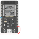
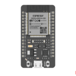
- ESP32 DOIT DevKit v1
- Single Channel Relay Module
- Breadboard and jumper wires
- USB cable
- Small DC load (like 5V LED bulb or motor)
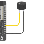
Circuit Diagram
- Relay VCC → ESP32 3.3V (some modules may require 5V, check your relay specs)
- Relay GND → ESP32 GND
- Relay IN → ESP32 GPIO 23
- Relay COM → One wire of the load power supply
- Relay NO (Normally Open) → Load device (e.g., bulb, fan)
- Other load wire → Power supply directly

Arduino Code
// Relay Module with ESP32 DOIT DevKit v1
// Relay IN pin connected to GPIO 23

int relayPin = 23;  // Relay connected to GPIO 23

void setup() {
  Serial.begin(115200);
  pinMode(relayPin, OUTPUT);  // Set relay pin as output
}

void loop() {
  Serial.println("Relay ON");
  digitalWrite(relayPin, HIGH); // Turn relay ON
  delay(2000); // 2 seconds delay

  Serial.println("Relay OFF");
  digitalWrite(relayPin, LOW); // Turn relay OFF
  delay(2000); // 2 seconds delay
}
Step-by-Step Code Explanation
Define Relay Pin
int relayPin = 23;
Relay is connected to GPIO 23.
Setup Function
pinMode(relayPin, OUTPUT);
Sets relay pin as output.
Loop Function
digitalWrite(relayPin, HIGH);
delay(2000);
digitalWrite(relayPin, LOW);
delay(2000);
Turns relay ON for 2 seconds, then OFF for 2 seconds repeatedly.
Real-Life Applications of Relay with ESP32
- 🏠 Home Automation – Turn on/off lights, fans, and appliances.
- 🌱 Smart Agriculture – Control water pumps and irrigation systems.
- 🏭 Industrial Automation – Operate heavy motors and machinery.
- 🔒 Security Systems – Control sirens, alarms, or door locks.
- ⚡ Energy Management – Schedule loads for efficient power use.
Troubleshooting
| Problem | Cause | Solution |
|---|---|---|
| Relay not switching | Wrong wiring | Check VCC, GND, IN connections |
| Relay always ON | Module requires LOW to activate | Invert logic in code |
| Load not working | Wrong COM/NO wiring | Reconnect load properly |
| ESP32 resets when relay switches | Current surge | Use external power supply for relay |
Can I connect a 220V AC appliance directly to relay?
Yes ✅, but you must be extremely careful with wiring. Use proper insulation and safety precautions.
Does the relay module work with 3.3V from ESP32?
Most modern relay modules work with 3.3V logic, but some need 5V supply. Check your module’s specifications.
What’s the difference between NO and NC in relay?
NO (Normally Open) → Load is OFF until relay activates.
NC (Normally Closed) → Load is ON until relay activates.
Can I control multiple relays with ESP32?
Yes ✅, ESP32 has multiple GPIO pins, so you can control several relay modules at once.
Why does my ESP32 restart when relay switches?
The relay coil causes a voltage spike. Use an external power supply or a relay module with optocoupler isolation.